Efficiency of an atmospheric engine
There is nothing such as a perpetuum mobile
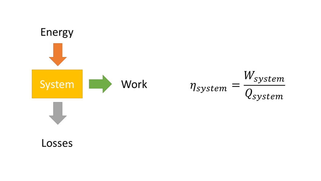
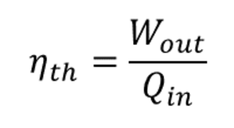
Efficiency is defined as the ratio of the useful energy delivered by a dynamic system to the energy supplied to it [1].
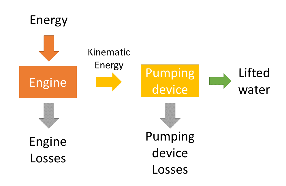
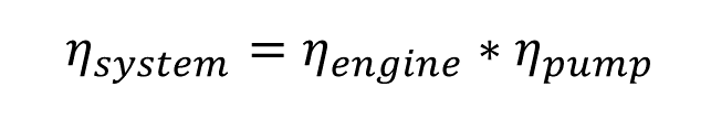
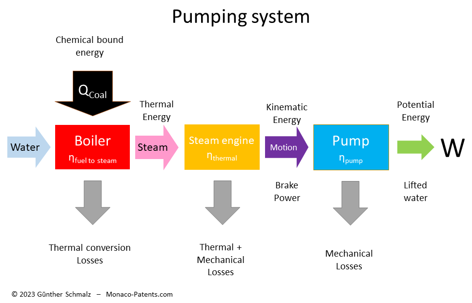
A typical water pumping device consists of an engine to create motion and a device that is propelled by the engine and uses the motion to lift water. The engine and the pumping device each have their own efficiency. The system efficiency is the product of the efficiency of the engine and the efficiency of the pumping device.
Pump efficiency
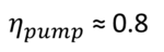
The power needed to lift water to a specific height was estimated using the following rule of thumb: take the height in feet from the water's surface to the point of discharge, add one foot and a half for each lift for the force needed to give the water its acceleration, and also add one-twentieth of the height for the friction of the piston. By using this information, we can actually determine how effectively a bucket pump would raise 8 feet of water. The input power for an 8-foot stroke therefore is equivalent to 8 ft + 1.5ft + 0.05*8ft = 9.9ft. The efficiency ηpump is consequently 8/9.9, or around 0.8.
The fact that it was regarded as best practise to load steam engines with a column of water equal to roughly half of atmospheric pressure [20] suggests that mechanical losses, including speed tradeoffs, were at a level of about 50%.
Four causes for the mechanical drawbacks are listed in one of the first books [21] on steam engines.
- Inertia of the moving parts, especially of the beam with its arch-head and chains
- Immersion of the pump rods into the water
- friction of the piston and other parts
- structure of the pumps
From a system perspective, these causes are the primary mechanical losses of the system "steam engine + pump". Causes 1 and 3 are fundamental mechanical losses of the steam engine itself, whereas causes 2 and 4 are mechanical losses of the pump itself. As the pump losses depend on the height to which the water is pumped, it is crucial to first establish the amount of power needed to raise the specified amount of water before determining the size of the steam engine that could handle the requisite power.
We must bear in mind that the bucket's stroke is 8 feet, but with numerous strokes, the pump might raise water as high as 25 fathoms (150 feet) or 30 fathoms (180 feet). For greater lifting heights, the right number of pumps needed to be put in sequence, with the lowest pump pouring water into a first cistern, the pump above pumping the water from this first cistern to a second cistern, and so on until the water is on the surface. [Tedgod page 279]. For a 100 fathom deep mine this lowers the pump efficiency to η = 0.84 ≈ 0.4, or 40%.
The diameter of the pumps were seldom chosen bigger than 16 inches. If a greater quantity was required it was found it was better to add a second pump than to increase the diameter beyond 16 inches. [Tedgod page 279].
Optimizing system efficiency
In internal combustion engines the liberation of chemical bound energy is an integral part. In order to turn water into steam as the energy source for steam engines, steam engines require an external boiler. The efficiency to convert the chemical energy contained in coal into steam, or the boiler efficiency, was actually a significant source of energy losses in the beginning. As the steam engine efficiency and boiler efficiency are not directly related, it makes sense to improve each of them separately.
In historical reports on steam engines, the boiler was considered part of the engine. Therefore, any calculation of the efficiency based on historical data must be cleaned up by the fuel-to-steam efficiency of the boiler to compare the efficiency of historical steam engines with the theoretical maximum thermal efficiency of that type of engine.
Heat
At the time of Watt, the concept of heat was still in its infancy. Watt and his contemporaries were unaware of the extent to which they could put the heat generated by burning coal to productive use, and they gave it little thought. Although James Watt approached the inefficiency of Newcomen's steam engine scientifically, his role as one of the founding fathers of what is called later the science of strong>thermodynamics was never acknowledged [7], probably because he did not make his research results public. James Watt rather kept his knowledge as a trade secret and discussed it only with business partners and close friends. For instant, Watt conducted experiments to determine the specific heat of some substances in relation to that of water, etc. [8].
But it wasn't until 1825 that a French journal reported on experiments by Nicolas Clément, a professor of chemistry at Paris' Conservatoire des Arts et Metiers on measuring heat. Clément coined the term "calorie" to denote the quantity of heat required to raise the temperature of 1 kg of water by 1°C and compiled a table of combustible materials and their heating values.
The definition of a calorie was changed to the amount of energy needed to raise the temperature of 1 g of water by 1°C when it was added to the meter kilogram second (m-kg-s) system. Therefore, to translate Clément's measurements into units that are comparable to those used today, the heating values in the above table actually should be multiplied by a factor of 1000 or read as 1 kcal. However, as the values are written in the French way, with a comma representing the decimal point, they are correct when English punctuation rules are applied.
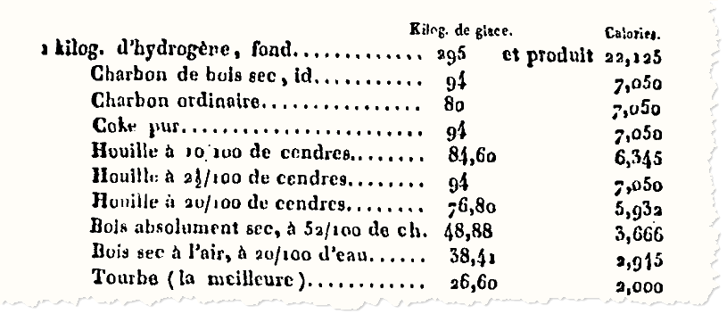
The heating values listed in the heat tables were either determined using stoichiometric calculations or by measuring the amount of fuel burned in pure oxygen. They represent the upper boundary of heat that can be extracted. Using air with a 19% oxygen concentration lowers the heating efficiency as well as the hydrogen that is burnt to water. If the water is not reclaimed by condensation, then as a function of the content of hydrogen in the chemical composition of the fuel, about 10% is lost as latent heat through the furnace.
The losses of latent heat (condensation losses) are a function of how much hydrogen the fuel contains. For this reason we distinguish today between Higher Calorific Value (= Gross Calorific Value - GCV = Higher Heating Value - HHV) for cases where the heat contained in the water vapour is completely recovered and Lower Calorific Value (= Net Calorific Value - NCV = Lower Heating Value - LHV) for cases where the products of combustion contains the water vapour and the heat in the water vapour is not recovered.
If you have a modern condensing boiler in your home the latent heat that is contained in the vapour of the flue gases is reclaimed. This is only possible when the flue gas temperature is kept below boiling temperature of water. In this case an efficiency of 94% can be achieved. But, this is not possible if you want to create steam with temperatures above 100°C.
Boiler efficiency
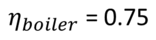
The proportion of total energy that a boiler uses to produce usable heat is known as its energy efficiency. I have not yet discovered any contemporary historical references mentioning boiler losses. It is reported [12] that the efficiency of egg-ended boilers was at 34%. No time is mentioned. A high pressure boiler operating in the range between 1.4 and 3.5 barg (gauge pressure is measured against the ambient pressure) constructed around 1810 by Trevithick is said to have reduced the Dolcoath mine's coal bill from £1000 to £612. Assuming the coal price and the produced pressure was the same that is an improvement of (1000-612)/612 = 63.4%.
Modern boilers, for example, fueled with diesel under maximum continuous rating, have an efficiency of 83%. The loss of 17% is made up of 8% loss due to sensible heat in dry flue gases, 8% loss due to enthalpy in the water vapour (latent heat losses, as explained above) and 1% loss due to radiation, convection and conduction. [14]. In Watt's days also the flue gas temperature was higher. For instance, with a flue gas temperature of about 316°C above the temperature in the boiler room the losses by sensible heat in the flue gases increase from 8% to 24% [15].
Maximum thermal efficiency of a heat engine
The first law of thermodynamics (law of conservation of energy) states that in any isolated system, one cannot create new energy, i.e. one cannot create with a given energy more energy than there was in the beginning. As a result, the thermal efficiency can never be greater than one, or 100%.
In 1898 a committee of the Institution of Civil Engineers of Great Britain proposed to use the expression “thermal efficiency” for the ratio between the heat utilized as work on the piston and the heat supplied to the engine. [60]. According to this definition, any internal mechanical losses that reduce the work delivered at the crankshaft have no impact on efficiency. As a consequence, even though a device with internal friction losses so high that they prevent it from performing any work would appear to be rather efficient. Today, thermal efficiency is defined as the ratio of the useable work produced by the steam engine to the heat supplied to the engine, or in other words, heat energy that is transformed into work.
Yet, Watt lacked the tools necessary to calculate how near or how distant the boiler's efficiency was from its theoretical maximum.
Carnot efficiency
When James Watt had the idea to use a separate condenser to increase the efficiency of a Newcomen steam engine, he had already understood that the priority was to prevent heat loss. He had no idea how close or how far away he was from an ideal heat engine. In 1824, the year before Prof. Clément's discoveries were published, Nicolas Carnot, who had worked and had become a friend of Prof. Clément, put forth his theory on the maximum efficiency a heat engine operating between hot and cold reservoirs could achieve. The Carnot cycle is the most effective heat engine cycle permitted by physical laws, but practical heat engines, which must operate at a reasonable speed, will always range below this efficiency.
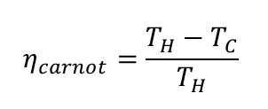
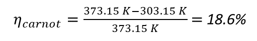
In this equation, TH stands for the hot reservoir's temperature in Kelvin, and TC for the cold reservoir's temperature in Kelvin. Accordingly, for a heat engine running on steam at 100 °C the hot reservoir temperature TH = 373.15 K. Assuming a condensation temperature of 30 °C the cold reservoir temperature becomes TC = 303.15 K. The maximum Carnot efficiency therefore is
Maximum efficiency of an atmospheric engine
From a thermodynamic perspective, we can view the Savery fire engine's slow operation—one working cycle per minute, as an almost static process. Therefore, it is possible to determine the maximum efficiency of such an atmospheric engine using the physics laws that are currently taught in secondary schools.
In the following calculation we do not account for heat losses, friction in the water pipes, or the boiler's efficiency. We also temporarily ignore any heat transfer from the steam to the vessel or from the vessel to the steam while the steam is condensing, even though this is the primary cause of atmospheric machines' inefficiency.
Our atmosphere exerts a mean pressure of 101.325 kPa at sea level. Air pressure changes will infrequently exceed 5% or 7%, even in the case of severe weather.
We now perform a straightforward assessment to determine how much work W it takes to completely transform 1 kg of water into 1 kg of steam and how much work this 1 kg of steam can accomplish when it is condensed. We begin with 1 kg of water with a temperature of 30°C, assuming that a boiler is fed by water (hot water well) retained from condensation. It requires (100°C - 30°C) ∗ 4.2 kJ = 294 kJ to heat 1 kg of water from 30°C to boiling. We need to add 2265 kJ of energy for the phase change in order to completely convert 1 kg of boiling water into steam at 100°C. With 2550 kJ heat altogether 1.672 m3 of steam will be produced at 100 °C.
1822, Robinson admits that they had not yet required the knowledge of the quantity of heat that is contained in steam in a latent form. It is obvious that an excess of injected water is cooling the piston and cylinder too much, so that steam is wasted during the next rise of the piston. Robinson remarks that Mr. Watt must have acquired valuable information by means of a barometer and expresses his hope that Watt would not withhold this information from the public. [5] But Watt did not rise to the bait and did not make an annotation in this respect.
In order to condense steam quickly Newcomen sprayed cold water into the vessel. If we take water that been raised from the pit, it could be as cold as 8°C. A complete condensation of 2265 kJ requires 2265 kJ / (92°C ∗ 4.2 kJ/K) = 5.9 kg of water, so there is at least 6 times more water available than required for boiler. A
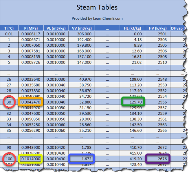
In an isolated system, i.e. no heat transfer occurs into the system or out of the system, water, as any other liquid, is in a thermodynamic equilibrium with vapour above the water level. This is due to the fact that in a state of thermodynamic equilibrium, an equal number of water molecules condense and vaporise. As a result, a certain percentage of the total water content will always exist in a gaseous phase, as few as it may be, as a function of temperature, producing a gas pressure. Complex formulas can be used to calculate this pressure, but they are too laborious for use on a regular basis. Therefore, the pertinent values have been measured and stored in tables, the so-called steam tables, for all technical substances of interest, particularly water.
Steam tables indicate that this vapour pressure at 30°C is 4.25 kPa. After condensation, the vessel's pressure difference with the atmosphere is therefore 101.325 kPa - 4.25 kPa = 97.1 kPa. This limits the amount of water the vessel can "suck" in. At 30 °C, there isn't much of a difference, but if the condensed water in the vessel is, say, 90 °C, the steam pressure would be 70 kPa, meaning the pressure difference to the atmosphere would only be 30%.
A pressure of 97.1kPa equals the pressure exerted by a 9.90-meter-tall- water column. This is the highest point at which water can be pushed into the vessel by the force of the atmospheric air pressure. The following is a general formula to determine how high water can be raised by a pressure difference of p:
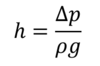
with the standard gravity g = 9.80665 m/s2 and the density ρ = 999.8 kg/m3 of water at 8°C and atmospheric pressure.
Recall that at 4 °C, water has its maximum density of 1000.0 kg/m3. The density difference at 8°C is negligible in this case. But I wanted to make clear that, generally speaking, measurement circumstances affect a material's physical properties. We should at least be conscious of them even if we choose to ignore them.
With 1kg of recondensed steam 1,672 kg of water could be raised to a maximum height of 9.90m and do work of 1672 kg ∗ 9.80665 m/s² ∗9.90m.
To prevent rounding errors we can rearrange the formula and eliminate the gravity constant. The similarity between this formula and the formula to calculate the work required to compress or expand an ideal gas volume in a quasi-static process is not a coincidence:
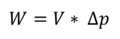
In the above formula V is the volume of recondensed steam and ΔP is the pressure difference before condensation and after condensation.
With this formula we calculate the maximum work Wmax that can be achieved by recondensing 1kg of steam = 1.6718m3 from normal atmospheric pressure patm = 1013.25 kPa to water of 30°C (P30°C = 4.247 kPa) as
1.6718 * (1013.25-4.247) kNm = 160.58 kNm = 160.58kJ
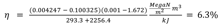
When efficiency is calculated as the ratio of work produced to work (heat) consumed, an atmospheric engine's efficiency can reach a maximum of 160.58 kNm / 2550 kNm = 0.063 or 6.3%.
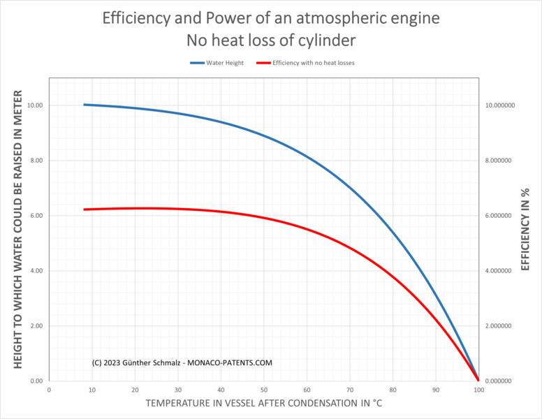
The temperature of the recondensed water affects efficiency, as we can see in diagram 1. Diagram 1 illustrates the effectiveness and maximum depth to which a Savery pump device can "suck" water. The column of water drawn into the pipes and the vessel balances out the atmospheric pressure. The smaller the pressure difference inside the vessel is, the slower the water flows into the vessel at the end of a pumping cycle. Therefore, efficiency has been sacrificed for speed, which means that the operator restarted a pumping cycle before the pressure difference had been fully utilised, i.e. the vessel had been filled to the maximum level possible. According to reports, Savery's engines were used to lift water up to a maximum height of 22 feet (6.70m). Diagram 1 shows that the maximum efficiency drops to 4.8% at that level. That would imply that speed was obtained at the expense of 25% of efficiency.
We should be aware that this approach as not perfect, as for example the specific heat is not linear over the temperature range but is a function of temperature and pressure or volume, respectively. A better way to do thermodynamical calculations is to use steam tables.
Using steam tables
In steam tables, we find the internal energy U of a substance (not shown in the table above). A body's internal energy is the sum of all its microscopic kinetic and potential energies. It's difficult to determine the absolute value. In thermodynamics, however, our main focus is on how much a change in a system's internal energy affects its temperature or how much it affects its state, such as when it changes from a liquid to a gas. The steamtables thus display the internal energy U with respect to an initial value, which may be chosen at random, since the reference value is automatically subtracted from the calculation when calculating the difference between two values based on the same reference value. However, it makes sense to use the number 0 as a reference point for the lowest temperature at which water is a liquid, i.e., Uwater @ 0°C = 0.
The internal energy U and the work added to the system by adjusting the pressure and/or volume of the system are added together to form a body's enthalpy H. If heat is applied to a liquid, it expands if there is room for it to do so in addition to changing its temperature to a higher value. Otherwise, if the volume is fixed, the liquid will experience an increase in pressure. If the liquid is permitted to change its volume, we must account for the work that volume expansion does. For a liquid like water, the work required for volume expansion is quite minimal. The internal energy U and enthalpy H of water at 100 °C are 419.06 kJ/kg and 419.17 kJ/kg, respectively. Thus, we can see that only 0.11 kJ/kg of work is required to expand water. On the other hand, steam has an internal energy of U = 2,506 kJ/kg and an enthalpy H = 2,675.6kJ/kg at 100 °C.
As in an atmospheric engine, we allow the volume to change, we use for our calculations the enthalpy H.
To determine the amount of energy required to turn 1 kg of water at 30 °C into 1 kg of steam of 100°C we first check in the steam table the enthalpy for steam at 100°C, which is 2676 kJ/kg (surrounded by a purple frame in above steam table). Then we look up the enthalpy for water of 30°C, which is 125.70kJ/kg (surrounded by a yellow frame in the above steam table). The difference, (2676 - 125.70)kJ/kg = 2550.3kJ/kg is the work for changing 1kg of water from 30°C to 1kg of steam at 100°C.
The difference between 2550 kJ, which we calculated above without steam tables and 2550.3 kJ calculated with the steam tables is negligible. We most likely just got lucky that rounding errors were balanced for the given figures. However, going forward, we'll base our calculations on utilising the values from the steam tables.
P-V-diagram
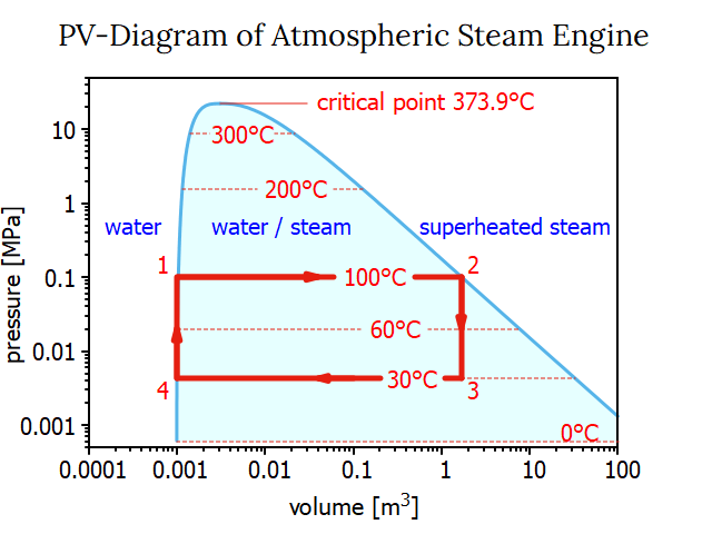
James Watt devised an instrument called the indicator to visualize the power actually exerted by his engines in the course of a cycle. The position of a working piston within a cylinder is proportional to the volume it is enclosing. As a result, at any point in the cycle, the piston's position provides a clear representation of the volume enclosed by the working piston. By recording the actual pressure at any given working piston's position, a so-called pressure-volume diagram, or P-V diagram, is created. We can also establish such a PV diagram on basis of the steam tables, as it is shown below.
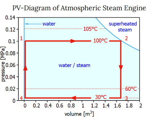
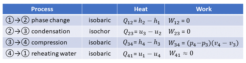
In the PV diagram, different states (1, 2, 3, and 4) are indicated by red numbers. At the start of a cycle in state 1, the boiler's water is boiling at 100° at atmospheric pressure. During process 12, more heat Q12 is added to the water that is already boiling, causing it to turn into steam at 100°C and atmospheric pressure. The steam tables may be used to determine the necessary heat Q12 for process 12 as previously demonstrated: Q12 = 2269.5 kJ/kg water. Because at this stage there is no pressure difference acting on the piston no work W12 is done by the system or added to the system: W12 = 0.
A process that maintains a constant pressure is referred to as an isobaric process. In PV diagrams, isobaric processes are always represented by horizontal lines. State 2 of the PV diagram shows that the volume of the steam is about 1670 times greater than that of the liquid phase of boiling water.
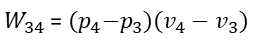
We go through two processes when we add cold water to the steam at state 2. First, Process 23 lowers the steam temperature to 30 °C, which causes the working cylinder's pressure to drop to 4.246 kPa (or 0.042 atm). The total heat change Q23 is the difference in enthalpy (u3-u2) for lowering the steam's temperature at a fixed volume (!) = 90.1 kJ/kg of water. A thermodynamic process taking place at constant volume is referred to as an isochoric process, or sometimes also called as an isometric process or constant-volume process. Again, no work is done. W23 = 0. The condensed steam is then transformed into liquid water at the same temperature in process 34, which lowers its volume at a constant temperature. Thus, it is an isobaric compression and process 34 creates the following work:
The table below is a summary of the Heat and Work involved in each process step:
Inserting the relevant process steps in the general formula for efficiency we have for the work gained from the process W23 and for the Heat input the heat Q41 for heating the water from condensation temperature to boiling temperature and Q12 for the heat for the phase change from boiling water into steam of the temperature of boiling water.
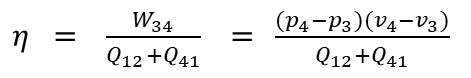
Or with p4 for the vapor pressure at 30°C, p1 the atmospheric pressure, v4 the volume of 1kg of water at 30°C (= 1.00441 liter or 0.001 m3), the volume of steam at 100°C, Q41 the heat for heating water from 30°C to 100°C, and Q12 for the vaporization heat for transforming 1kg of boiling water into 1kg steam of 100°C we finally arrive at:
Both scales — the scale for volume and the scale for pressure — in the PV-diagram shown above are linear. Watt anticipated that there will be a point when the phases of water and steam would combine. Nowadays, this culmination point is referred to as the critical point. In a phase diagram that includes the critical point, still with linear scales for pressure and volume the working area of the atmospheric steam engine would be quite tiny. So, it is customary practice to display the working area of a steam engine in a PV-diagram with a double logarithmic scale:
Considering heat losses by cooling the vessel from the outside

In the earliest iterations of a Savery engine, the vessel E, also known as a receiver by Savery, was cooled from the outside by opening a tap M and allowing cold water to flow over the vessel, as can be seen in the picture to the right. The entire vessel must be cooled in order to cool the steam inside of vessel E. This implies that after the water has been sucked in, the entire mass of the vessel must be reheated.
A Savery engine example shows a receiver in the shape of a cylinder with a 2 foot (0.61 m) diameter R and a 7 foot (2.1 m) height H. (2.13m). Although the thickness D of the cylinder's walls is unknown, statements for other vessels suggest that D = 1 inch (2.54cm) might be a reasonable assumption.
Assuming that the given values describe the external dimensions, the volume inside the cylinder is
V = (R-D)²∗π∗(H-2D) = (0.61/2 m - 0.0254 m)²∗π∗(2.13m-2∗0.016m) = 0.511m³
The total volume of cylinder is:
V = R²∗π∗H = (0.61m)²∗π∗2.13m = 0.623m³
Assuming the hollow cylinder is made of brass, which has a density of 8.73g/cm³ then the mass of the cylinder is
(0.623-0.511)m² ∗ 8.73 * 10³kg/m³ = 977kg
When the receiver is filled again with steam, the steam must reheat the cylinder to 100°C; otherwise, the steam would simply condense on the walls of the cylinder. Brass has a specific heat of 380 J/kg, meaning that it requires 371.3 kJ of energy to reheat it for every 1°C difference. The energy required to heat the cylinder by 40 °C is 371.3 KJ * 40 °C = 14,852 KJ if we assume that the cylinder walls were cooled down to 60°C to condense the steam inside the cylinder to the water of 60 °C. As we can see, the heat required to reheat the brass cylinder is 6.6 times greater than the heat to turn water from 100°C into steam of 100°C.
Although receiver or cylinder outer dimensions are frequently documented, the thickness of the cylinder walls has never been reported. Hollow iron items, such as pipes and cylinders, started to be inexpensive and easy to find after Abraham Darby, around 1713, started using coke rather than charcoal to smelt iron in a blast furnace and use it as cast iron in sand moulds. This decreased the initial costs of installing steam engines. By 1740, cast iron cylinders could were available from Coalbrookdale for 20 to 30 pounds each as opposed to paying 250 pounds for a brass cylinder. [70]
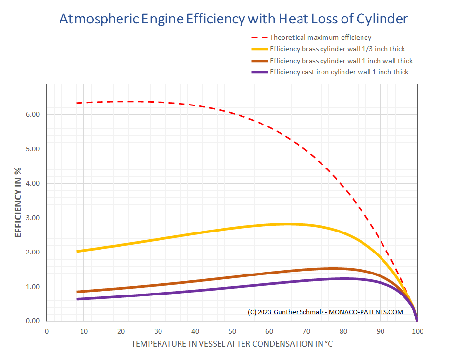
John Theophilus Desaguliers, a British natural philosopher, engineer, who was admitted to the Royal Society in 1714 as Isaac Newton's experimental assistant, lived from 12 March 1683 to 29 February 1744. [71] He cautioned that cast iron cylinders could not be produced with a wall thickness of less than an inch, although brass cylinders of the biggest size have been made with walls as thin as 1⁄3 of an inch. Hence, he argued that using iron cylinders would result in a 1⁄10 or even 1⁄8 decrease in pumping efficiency. [72]
The graphic below compares the losses that occur when brass and iron cylinders with inner diameters of 50 inches and inner heights of 8 feet are cooled to a certain condensation temperature on the exterior. At 70°C for example the efficiency of a brass cylinder of one inch wall thickness is by a factor to 1.28 better than the efficiency of a cast iron cylinder of the same wall thickness. Yet the efficiency improves compared to the cast iron cylinder by a factor of 2.38 when the wall thickness of the brass cylinder is reduced from one inch to a third of an inch.
The efficiency radically drops when the receivers with a smaller volume are used, as then the ratio of the volume brass to the volume of enclosed steam is less favourable.
One statement says that the interior space of a cylinder of a Newcomen steam engine was usually cooled by the injection between 140 and 160 degrees of Fahrenheit's thermometer (60°C - 71°C) [3]. Watt himself states that by examining the hot water issued from the eduction pipe of several Newcomen's engines the temperature varied between 142°F (61°C) and 174°F (79°C) [4]. In case of 70°C the Carnot efficiency would drop to 8%.
Efficiency of Savery's fire engine
Unfortunately not a lot of information on the Savory engine could be found that has complete information to calculate the efficiency of the Savery engine.
In 1718, three years after Savery's death a gardening book describes a Savery engine that was installed by Savery around 1771.
When this engine begins to work you may raise four receivers full of water in one minute which is fifty-two gallons raised 58 feet. At that rate, in an hour's time, may be flung up three thousand one hundred and twenty gallons ; which is above eighty-six barrels. ... the quantity of coal required for each working is about half a peck ; so that the expense will be very inconsiderable in comparison to what the carriage of water upon horses would amount to and in such countries where wood is plenty the expense would be much less. [4]
Raising 52 gallons of water by 58 feet equals 236kg of water raised to 17.7m. The work done by the Savery machine in one minute is 236kg ∗ 9.80665 m/s² ∗ 17.7m = 41kJ in one minute or 41kJ ∗ 60 = 2548 kJ = 0.68kWh in one hour. This equals 0.68kW or 0.92 horse power.
Unfortunately it is not clear what the words "for each working" means. As the source mentions that four receivers may be filled in one minute, this might be considered as one working. In this case half a peck of coal burnt in one minute is 30 pecks in one hour or 7.5 bushels in an hour. This is 2355kWh of heat.
The efficiency in this case would be 0.68kWh / 2355kWh = 0.03%.
This would be a terrible efficiency and cannot be considered as an inconsiderable expense in comparison if horses would have carried the water uphill. Unfortunately, we have to drop this calculation due to the insufficient information given.
Farney reports also on two experiments performed by Smeaton on suction only machines of Savery:
Smeaton made trial of two engines, which were put up in Manchester in 1774, by Mr. Rigley, to work water-wheels. They operated by suction only, and were very like that last described.
The first had an upright cylindrical receiver, 16 inches diameter, and about 22 feet high. It discharged the water at 14 ft. above the water in the well, and about 8 ft. beneath the top of the receiver. It made 12 strokes per minute, and each stroke filled the receiver about 6 feet high. Now a cylinder, 6 ft. long and 16 inc. diameter, contains about 8 1/3 cub. ft. x 12 strokes = 100 cub. ft. of water per minute x 14 ft. = 1400 cub. ft. raised 1 foot : this divided by 528 cub. ft. for a horse power, gives 2 2/3 horse power.
This engine consumed 3 hundredweight of coals in 4 hours, or 3/4 of a hundred-weight (which is exactly a bushel) per hour. In that time it exerted a sufficient power to raise (1400 x 60 =) 84,000 cub. ft. to a height of 1 ft. The weight of this water, at 62 1/2 pounds to a cub. ft. would be 5,250,000, or 5 1/4 million pounds weight, raised to a height of 1 foot by the consumption of a bushel of coals, weighing 84 pounds.
The other engine was larger. The cylindrical receiver was 2 ft. diameter withinside, and 7 ft. high. It delivered the water at 19 ft. high above the surface of the water in the well, and it made 7 1/4 strokes per minute, each stroke filling the receiver 6 ft. high. The quantity is 18 3/4 cub. ft. per stroke, or 136 cub. ft. per minute, raised 19 ft. ; that is, very nearly 5 horse power.
This engine consumed 32 cwt. of coals in 24 hours, or 1 3/4 bushels per hour; and at that rate, each bushel would raise nearly 5 1/2 million pounds weight 1 ft. high.
As neither of these engines were constructed with the best boilers, such as, have since been brought into use in modern steam-engines, it is probable that a. greater effect might be produced from the fuel.
The first machine raises 100 cubic foot of water per minute = 2.8317m³ per minute by 14 feet (4.27m). This is equivalent to a power of 1.97kW (2.65 horse power) or a work of 1.97kWh per hour. In order to do this work, 24 bushel of coal had been burnt in 24 hours = 7,534 kWh. Thus we arrive at an efficiency of 1.975Wh*24/7535kWh = 0.63%.
The second machine raises per minute 3.83m³ of water to a height of 5.79m. This is a power of 3.65kWh or 4.89 horse power. By burning 42 bushel of coal per hour we arrive at an efficiency of 0.66%.
As both machines were put up 76 years after Savery's patent, we can assume that the steam in the vessel was condensed by injecting water into the inside of the steam cylinder. Despite the bad efficiency they might have been chosen because their construction was much simplier than a Newcomen machine and therefore they must have been much cheaper to buy. The also have a mechanical loss. The first machine for example draws water up to 22 ft, but releases the water at 14 ft height above the water in the well. Assuming that the pressure of the 8 ft of water in the cylinder were not used, the energy of the water pumped above the release level of 14 ft was lost. The engine actually pumped the water to a mean level of 14 ft + 8/2 ft = 18feet. The thermal efficiency of this Savery pump was 0.63% * 18/14 = 0.81%. The mechanical efficiency of the pump action was 14ft/18ft = 77.8% because the water was raised to the mean level of 18 ft, but released on 14 ft.
We will see that sometimes we can do the same calculation with the Newcomen and Watt style steam engines, where the pumps are separate devices, but the consumption and the power is calculated on basis how many pounds of water had been raised, i.e. the system efficiency.
--------------------------------
[1] https://www.merriam-webster.com/dictionary/efficiency
[2] Anonymous: Cours de Chimie appliquée aux arts. Le Producteur. 1825, 1: 574-587. available on gallica.bnf.fr
[3] John, Farey, A treatise on the steam engine : historical, practical, and descriptive, London 1827 available INTERNET ARCHIVE, page 132
[4] John Robison, System of Mechanical Philosophy, 1822, with annotations/corrections of James Watt, footnote on page 96.
[5] John Robison, System of Mechanical Philosophy, 1822, with annotations/corrections of James Watt, page 97.
[5] Richard Bradley, New Improvements of Planting and Gardening, Both Philosophical and Practical, 1781pages 175-179
[5] Bortolin, Vitor & Lemos, Bernardo & Amaral, Rodrigo & Freire, Cesar & Meneghini, Julio. (2021). Thermodynamical model of an atmospheric steam engine. Journal of the Brazilian Society of Mechanical Sciences and Engineering. 43. DOI: 10.1007/s40430-021-03209-9
[7] Mitrovic, J. (2022), Some ideas of James Watt in Contemporary Energy Conversion Thermodynamics. Journal of Modern Physics, 13, p. 385-409. https://doi.org/10.4236/jmp.2022.134027
[8] Britannica: Thermodynamics
[11] Endress+Hauser Flowtec AG, CH-4153 Reinach/BL, Steam Handbook
[12] M.V. Murray, "The Shell Boiler: A Historical Review", Journal of the Institute of Fuel, Vol. 32 (224), 425-433; referred to in [11], page 7.
[13] L.T.C. Rolt, The Cornish Giant: The Story of Richard Trevithick, Father of the Steam Engine, London, 1960, The Camelot press, p. 168, referred to in [11], page 7.
[15] https://www.engineeringtoolbox.com/boiler-combustion-efficiency-d_271.html
[20] John Robison, System of Mechanical Philosophy, 1822, with annotations/corrections of James Watt, footnote on page 89.
[21] John Robison, System of Mechanical Philosophy, 1822, with annotations/corrections of James Watt, page 89/90.
[60] The Institution of Civil Engineers, THE THERMICAL EFFICIENCY OF STEAM-ENGINES; Report of the Committee appointed on the 31st March, 1896, to Consider and Report to the Council upon the Subject of the Definition of a Standard or Standards of Thermal Efficiency for Steam-Engines, available in the INTERNET ARCHIVE
[70] H.W. Dickinson, "A Short History of the Steam Engine", Cambridge at the University Press, 1939, page 54
[71] Wikipedia
[72] Desaguliers, Experimental Philosophy, vol. II, 1744, p. 536.